제목 없음
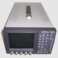
Analog Waveform Monitors
1740A Series • 1750A Series • 1760 Series
Features & Benefits
- Composite or Component Waveform Monitoring
- Composite Vector Display
- Picture Display
- Stereo Audio Display
- Time Code Phasing and Amplitude
- SCH and Color Framing Display
- Component Vector, Lightning, Diamond and Bowtie
Applications
- Analog Baseband Video Monitoring for Broadcast and Post Production
Applications
The 1740A/1750A/1760 Series make up a family of analog video waveform/vector
monitors with progressive features in support of today\'s demanding television
environment.
Each model in the series provides improved video performance and ease of
operation and incorporates application specific features. The family includes
the 1740A Series composite analog waveform/vector monitors, the 1750A Series,
which adds SCH and color frame verification capabilities, and the 1760 Series
for mixed format component/composite applications. (While the 1740A and 1750A do
provide basic component waveform monitoring capabilities with parade and overlay
displays, only the 1760 provides full component monitoring capabilities.)
Each series includes models for NTSC, PAL or dual standard NTSC/PAL
operation. For NTSC models, the last digit of the model number is \'0\' (1740A,
1750A or 1760); \'1\' for PAL (1741A, 1751A or 1761); and \'5\' for dual standard
NTSC/PAL (1745A, 1755A or 1765).
The family features a common, straightforward operator interface, allowing
the operator to take immediate advantage of the instrument\'s extensive feature
set. Each operating mode provides a full set of operating controls, clearly
labeled and within easy reach. Key controls are always available, with bezel
buttons and knobs identified by intuitive on-screen labels.
Selection Guide
Product Applications |
1740A Series |
1750A Series |
1760 Series |
|---|
Composite or component waveform monitoring |
X |
X |
X |
Composite vector display |
X |
X |
X |
Picture display |
X |
X |
X |
Stereo audio display |
X |
X |
X |
Time code phasing & amplitude |
X |
X |
X |
SCH & color framing display |
|
X |
Opt. SC |
Component vector, lightning, diamond & bowtie |
|
|
X |
All family members provide the following standard features:
Eight Video Inputs eliminate the requirement for external input
selectors, reducing total system cost in many applications. Since all eight
inputs are connected directly to the instrument, signals may be paraded,
overlaid or displayed in comparison modes not normally available with a simple
external switcher.
Waveform monitoring is analog for maximum waveform fidelity. There is
no digital processing of the displayed signal. The selected input may be
displayed in one or two line or one or two field sweeps on a continuous basis or
identified lines of any field may be selected and displayed. Multiple inputs may
be displayed at the same time or multiple filters may be applied to one input
for signal analysis. Time and voltage cursors may be activated and positioned
for reference or measurement.
Composite Vectorscope functions demodulate and display the color
components of the NTSC or PAL signal. A microprocessor controlled phase shifter
provides accurate vector positioning and eliminates readjustment when switching
between internal and external reference modes. Phase and amplitude cursors with
on-screen readout allow system setup to reproduce specific chroma values and
specific colors when luminance is similarly set using the waveform display
voltage cursors.
A Picture Monitor mode is provided for easy signal identification.
This is particularly useful when the instrument is used to monitor many sources,
as in a production suite or outside production vehicle. In waveform or vector
line select mode, a line bright-up marker in the picture display identifies the
selected line.
Stereo Audio Amplitude and Phase are monitored using a calibrated L/R
Lissajous display. The operator can quickly see that the program audio will be
properly reproduced on both monaural and stereo receivers. Correct phasing
between two audio channels is quickly verified by the direction of the display;
signal level (left + right) is confirmed relative to the CRT graticule; and
stereo separation (left - right) is displayed in quadrature to the level
display.
Audio frequency -3 dB bandwidth is 200 kHz. Phase match between the left and
right channels is better than 1 degree at 20 kHz. Input is high impedance
bridging, either balanced or unbalanced, to allow signal monitoring of existing
audio circuits.
This display of stereo audio is intuitive and easy to use and has gained wide
acceptance in new generation Tektronix vectorscopes.
Longitudinal Time Code is monitored in a frame rate display to allow
observation of amplitude, synchronization and phase with respect to reference
vertical. Synchronization is confirmed by the stationary display and time code
phase is easily determined by horizontal position of the time code sync word on
the CRT.
These monitors provide multiple display modes, allowing simultaneous
observation of the many important parameters that make up a television signal.
For example, vector, waveform and audio may be displayed together for an
indication of signal quality without operator intervention.
In the 1750A, or 1760 with SCH option, Subcarrier/Horizontal phase and
color framing are displayed graphically in the patented Tektronix polar SCH
display. Sync jitter over the field is displayed as a moving sync vector dot or
displayed as a timing error at a vertical rate to identify the relationship over
the field time. Correct color framing is quickly verified by the position of the
single sync vector dot relative to the color subcarrier vector when the monitor
is externally referenced.
The SCH phase of the reference signal is separately sensed to allow reliable
SCH and color framing comparison. Using this method of determining relative SCH
phase and color framing eliminates the requirement for a precise horizontal
timing match between the reference and measured signals and an external
color-field identification input is not required.
User Interface
Characteristic of current generation Tektronix instruments, an intuitive
operator interface allows full instrument utilization with minimal reference to
the provided user and maintenance manuals. Operating modes, any of eight video
inputs and key control knobs and buttons are always available for direct access
from the front panel.
To keep operation easy and straightforward, the 1740A, 1750A and 1760 family
\"learns\" the user\'s preferences for waveform, vector and picture modes (and SCH
in the 1750A and 1760 with the SCH option). Returning to one of these modes
restores the previous configuration. Changes to a mode configuration are easily
made using front panel buttons, supplemented by screen-labeled buttons and
knobs. Knob operations such as position, gain, phase, etc., are stored as
well.
The 1740A/1750A/1760 family is easily configured for special monitoring
applications, which may be stored in user presets for easy recall. For example,
a program line or off-air VITS may be set up as preset number 3. Preset number 3
could be named and later recalled to display line 19 of the selected input in 2H
sweep, with voltage cursors marking proper signal levels. Other presets could be
used to immediately access and display signals from other points in the system.
Different operators could quickly return to preferred monitoring setups after
specialized signal checks.
With eight loop-through video inputs, the 1740A/1750A/1760 family is a
versatile central point system monitor. This capability is particularly useful
in the production studio, where several machines, cameras and composite
input/output feeds are in use.
As a machine monitor, the instrument may be operated from a central control
panel, with waveform, vector (SCH and color framing with the 1750A Series and
1760 Series with SCH), audio, time code and servo signals easily observed.
High Performance Design
The control system, based on Motorola\'s rugged MC68332 32-Bit microprocessor
with internal coprocessing, facilitates instrument control and timing functions.
Flash EPROMs simplify updating the instrument to the latest firmware
configuration.
The 1740A/1750A/1760 family is based on completely new, high performance
analog video system electronics. Application Specific Integrated Circuits
(ASICs), developed by Tektronix specifically to maintain signal fidelity in a
television test instrument, handle internal signal routing and
amplification. Video performance is tightly controlled providing confidence that
the signal display accurately represents the signal under test.
As an example of this new video performance level, the series permits
observation of the video signal at up to x10 vertical and x25 horizontal
magnification. Any part of the signal may be positioned on screen in any
magnification. Overscan performance at any gain setting is virtually
distortion-free.
DC Offset (position match) between two or more displayed channels is within
1 IRE or 7 mV. Loop-through return loss is better than 40 dB to 10 MHz.
Operational Flexibility
Eight loopthrough video inputs may be connected to the rear panel of the
1740A/1750A/1760 Series, eliminating the need for a dedicated routing switcher
bus in many applications. Any of these inputs may be selected singly or in
combination from the front panel or via the RS-232 interface. Input selection
may also be included in preset configurations recalled via remote control
connector.
A separate external input may be selected to synchronize the display,
allowing relative SCH and color framing comparison between two input signals or
with the house reference. Because a separate SCH evaluation is done on the
reference signal, SCH and color framing displays are accurate over a wide input
range.
Signal standards can be automatically selected, NTSC 525/60 or PAL 625/50, in
dual standard 1745A/1755A/1765 models. A CRT graticule suitable for both
standards is provided. A microprocessor controlled phase shifter may be
activated to rotate the vector display to the correct position on the display.
Once set for each standard, the instrument displays the correct vector rotation
when the video standard is changed.
A new universal input power supply is a part of these monitors. AC mains in
the range of 90 to 250 V, 50 or 60 Hz, are accommodated automatically. This new
power supply will also operate from a nonsinusoidial supply, allowing battery
operation using an external, high efficiency switching inverter. A snap-lock
power cord appropriate to the country of use is supplied with each
instrument.
|