|
| |
|
| |
제목 없음
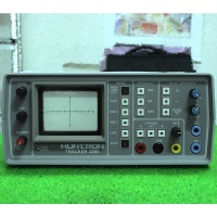
Tracker 2000 General Purpose
Troubleshooter
- Perfect for finding leakage or substrate damage
- Troubleshoot optocouplers and other gate-fired
devices
- Compare Multichannel outputs
- Test components and boards without power - ideal for
catastrophic failures.
- Get picture of a components overall health -
including intermittent problems
- Test gate-fired devices with a built-in pulse
generator
- Non-destructive testing
| Range
Parameters |
| Range |
Vs
(Vpk) |
Zs (k
ohms) |
Isc (m
Arms) |
Pmax
(mW) |
Pdiode
(mW) |
| High |
60 |
74 |
0.6 |
6 |
0.2 |
| Medium
2 |
20 |
27 |
0.6 |
2 |
0.2 |
| Medium
1 |
15 |
1.2 |
8.5 |
23 |
2 |
| Low |
10 |
54 ohms |
132 |
232 |
33 |
| Specifications |
| Input
Selection |
A, B, Alternate (variable
rate) |
| Test
Frequencies |
50/60 Hz, 400 Hz, 2000 Hz |
| Range
Selections |
Manual or Auto Scan, High Range
Lockout |
| Alternation
Rate |
Adjustable (0.5 to 10 Hz) |
| Pulse
Generator |
Level: 0 V to 5 V |
| DC Mode: + DC or -
DC |
| Pulse Mode: + Pulse, - Pulse, or
both; adjustable, duty cycle |
| Display |
2.8 in (7.0 cm) diag
CRT |
|
| |
|
|
|